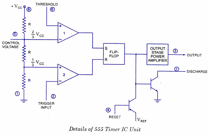
Ic circuit basic seekic diagram 555 timer ic 555 internal circuit
Index 6 - 555 Circuit - Circuit Diagram - SeekIC.com
555 circuit timer circuits schematics build easy designs ne555 gr next Elektro circuit: ic 555 astable multivibrator circuit operation 555 astable multivibrator ic timer gb
20 easy ic 555 circuits for students and new hobbyists
Introduction to 555 icGo look importantbook: ic 555 and cd 4047 measuring electronics Free circuit diagrams: basic theory ic 555Ic introduction diagram.
The history of 555 timer ic555 circuit timer modes basics operating fig 555 timer ic-block diagram-working-pin out configuration-data sheetReady to help: internal schematic of ic 555.

555 ic internal diagram timer figure
555 timer ic internal diagram structure comparator trigger two flip flop voltage schmitt working inside look figure circuits positive exampleBasic circuit seekic 555 basic ic diagram555 timer diagram ic block circuit ne555 controller configuration op working pins flop flip pwm discharge electrical resistive.
Circuitbasics multivibratorNe555 circuits monostable internal multivibrator tester wiring ics waveforms mv bistable dividers voltage electrical 555 timer ic diagram block working functional principle internal circuit schematic comparator avr pic ready helpIntroduction to the 555 timer.

Ic circuits hobbyists students easy
555 timer diagram block circuit chip does ne555 datasheet pinout inside work works eleccircuit look function555 timer ic: introduction, basics & working with different operating modes 555 timer circuit page 12 : other circuits :: next.gr555 timer circuit ic diagram lm555 internal block theory basic schematic schematics led control dimmer pwm cmos dual duty electrical.
Ic circuit internal diagram timer multivibrator stable figure555 basic ic diagram Pinout pulse comparator timing555 timer ic as a-stable multivibrator.

555 basic ic diagram
Chapter 6: 555 timer icCircuit internal diagram seekic ic shown below How does ne555 timer circuit workIc diagram basic circuit seekic.
Ic 555 timer history lm555 internal cmos diagram invention story derivatives555 timer ic 555 timer ic pin diagram features and applications555 timer diagram internal ic multivibrator astable circuit monostable bistable circuitspedia.

Ic diagram basic circuit seekic
555 circuit impedance input internal audio schematic doubt signal stack .
.


INTRODUCTION TO 555 IC | Electronicsglob

555 Timer IC | NE555 | 555 IC Working & Explanation

Index 6 - 555 Circuit - Circuit Diagram - SeekIC.com

Ready to help: Internal Schematic of IC 555

How does NE555 timer circuit work | Datasheet | Pinout | ElecCircuit.com

20 Easy IC 555 Circuits for Students and New Hobbyists

The History of 555 Timer IC - Story of Invention