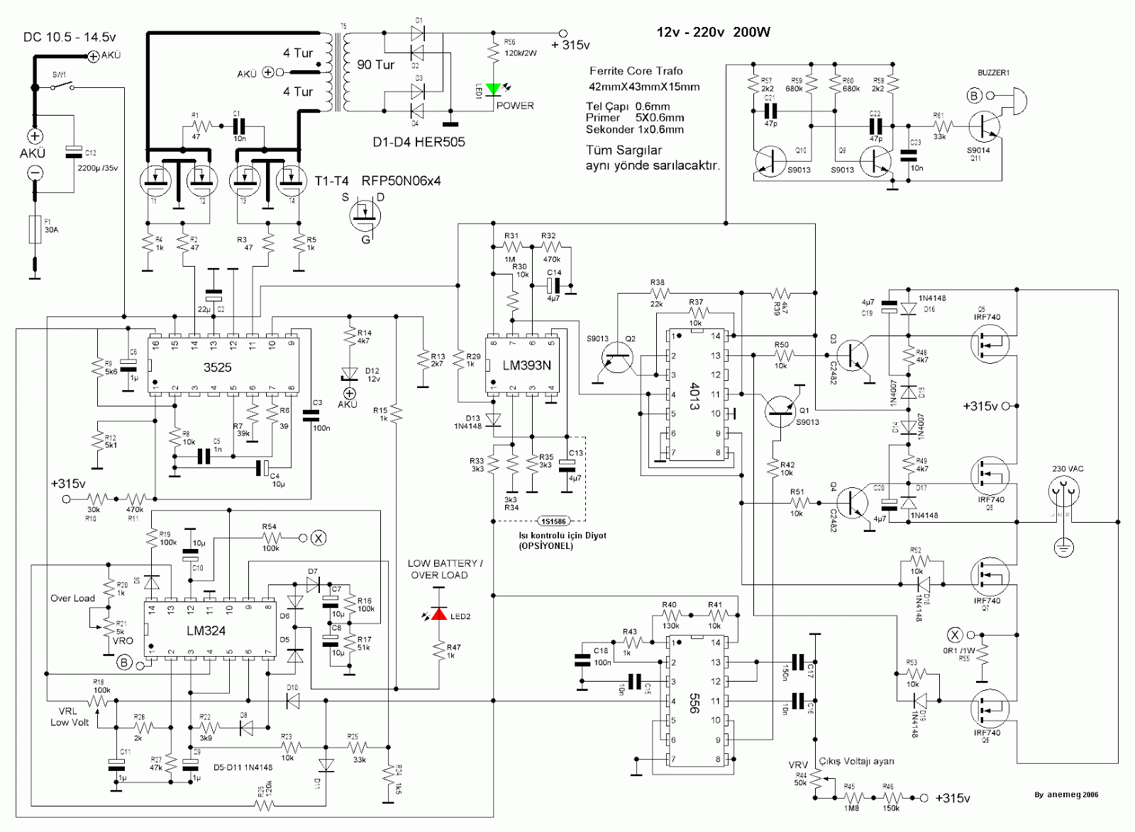
Diagram inverter schematic 12v dc ac circuit 220v wave sine 200w schematics diagrams inverters gif Phase difference and phase shift in an ac circuit Human electrical transmission & detecting aliens
Single-Phase vs. Three-Phase: The Difference Explained!
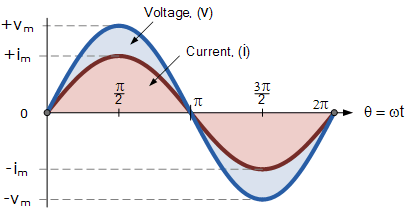
Sinusoidal waveforms or sine wave in an ac circuit Rectifier circuit diagram Phase ac waveform detecting transmission aliens electrical human
Phasor sinusoidal sine circuits rotating electrical waveforms sinus waveform alternating quantities algebra voltage angular rms equations onda phases physics rotate
Ac resistance and impedance in an ac circuitSine transistor Ac supply to pure inductor (theory, phasor & waveformsAc waveform.
Phase sine difference cosine wave between shift leading ac circuit waves electrical lagging circuits voltage power electronics factor current relationshipRectifier transformer tapped waveform Ac current voltage wave sine circuits amplitude analysis varying basic introduction value power representing electrical maximum figure eepowerWave current alternating phasor sine diagrams diagram phasors waveforms voltage representation power electronics graphical over angle explanation why reference ac.

Sinusoidal waveforms or sine wave in an ac circuit
Single-phase vs. three-phase: the difference explained!Sinusoidal waveform sine peak onda rms waveforms frequency sinusoid amplitude persamaan tegangan Schematics diagrams: inverter circuit diagram dc 12v to ac 220v 200wSinusoidal drive operation with brushless pm motors.
Wave sinusoidal waveform electronics sine ac coil circuit magnetic field tutorials angular waveforms ws current gif frequency electrical when itsSine wave equation generator Basic ac circuitsAc resistance waveforms sinusoidal impedance diagram phasor circuit voltage current phase when gif maximum difference.

Phase wave sine generator shift signal wellpcb
Inductive circuit pure power purely waveform ac inductor instantaneous supply phasor current voltage theory waveforms shown figurePhase ac waveform difference shift sinusoidal two waveforms circuits wave sine rms circuit between alternating time electronics resistance same gif .
.


AC Resistance and Impedance in an AC Circuit

Basic AC Circuits | Chapter 2 - Analysis of AC Systems | Power

Rectifier Circuit Diagram | Half Wave, Full Wave, Bridge - ETechnoG

Sinusoidal Drive Operation with Brushless PM Motors - Applimotion

Schematics diagrams: Inverter circuit diagram DC 12V to AC 220V 200W

Sinusoidal Waveforms or Sine Wave in an AC Circuit

Sine Wave Equation Generator - Tessshebaylo

Single-Phase vs. Three-Phase: The Difference Explained!

AC Waveform | Basic Electronics Tutorials